Manual Ultrasonic Defects Detectors Testing System
Ultrasonic Flaw Detection: Conventional and Phased Array Techniques
Ultrasonic flaw detection is a crucial non-destructive testing (NDT) method used across various industries to identify internal defects in materials. By utilizing high-frequency sound waves, this technique can detect flaws such as cracks, voids, and inclusions without causing damage to the tested material. There are two primary approaches to ultrasonic flaw detection: conventional ultrasonic testing (UT) and phased array ultrasonic testing (PAUT). Each method has its own advantages and applications, making them valuable tools in quality assurance and structural integrity assessments.
Conventional Ultrasonic Testing (UT)
Principles and Methodology: Conventional ultrasonic testing involves the use of a single transducer that emits and receives sound waves. The basic steps are as follows:
- Transducer Operation: A piezoelectric transducer converts electrical energy into high-frequency sound waves, which are introduced into the material.
- Sound Wave Propagation: These waves travel through the material and reflect off internal surfaces or defects. The time it takes for the echoes to return is measured.
- Data Interpretation: The received signals are analyzed to identify anomalies. A display, often an oscilloscope or a dedicated ultrasonic testing instrument, visualizes the data.
Applications: Conventional UT is widely used in industries such as aerospace, manufacturing, and oil and gas. Common applications include:
- Inspecting welds for integrity and flaws.
- Evaluating the thickness of materials, especially in pipelines and pressure vessels.
- Detecting internal flaws in castings and forgings.
Advantages:
- Simplicity: Conventional UT equipment is generally less complex and more cost-effective than advanced systems.
- Portability: The equipment is often lightweight and easy to transport, making it suitable for field inspections.
- Proven Reliability: This technique has a long-standing history of effectiveness in various applications.
Phased Array Ultrasonic Testing (PAUT)
Principles and Methodology: Phased array ultrasonic testing represents a significant advancement over conventional UT. It employs multiple transducer elements, which can be electronically controlled to emit and receive sound waves at different angles. The main steps include:
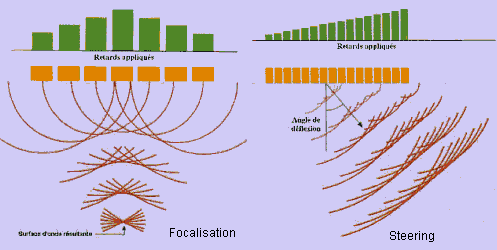
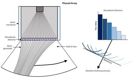
- Array Configuration: The transducer consists of multiple elements arranged in a linear or curved configuration, allowing for flexible beam steering.
- Electronic Focusing: Each element can be activated in a specific sequence, enabling the sound waves to focus at different depths and angles. This allows for more comprehensive coverage of the inspection area.
- Data Visualization: The data collected can be visualized in various formats, such as B-scans or C-scans, providing a more detailed view of the material's internal structure.
Applications: PAUT is used in more complex inspections where detailed information is required. Typical applications include:
- Inspection of complex geometries in aerospace components.
- Detailed evaluation of welds and joints in critical structural applications.
- Assessing the integrity of pressure vessels and heat exchangers.
Advantages:
- Enhanced Detection: PAUT can detect smaller and more complex defects compared to conventional UT due to its ability to scan multiple angles and focus on specific areas.
- 3D Imaging: The data visualization options provide a more comprehensive view of the internal structure, allowing for better assessment of defects.
- Time Efficiency: PAUT can cover larger areas more quickly, reducing inspection time and increasing productivity.
Comparative Overview
| Feature | Conventional UT | Phased Array UT |
|---|---|---|
| Defect Detection Capability | Suitable for general inspections | Superior for complex defects |
| Data Visualization | Basic (A-scans) | Advanced (B-scans, C-scans) |
| Inspection Speed | Slower for large areas | Faster with wider coverage |
Karl Deutsch Range of Ultra Sonic Testing System (Hand Held and Automated)
Karl Deutsch has the ultrasonic detector suitable for your testing application ranging from small handheld systems to large automated online system, whatever the testing requirement we could definitely configure it for you. An Ultrasnoic system contains a UT transducers, electronics, display and a mechanism to perform the scan.
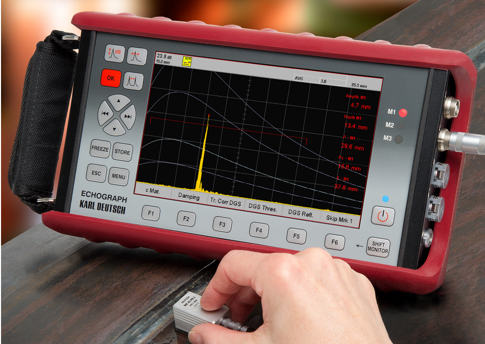
ECHOGRAPH 1095 Ultrasonic Flaw Detector: Product Overview
The ECHOGRAPH 1095 is an advanced manual ultrasonic testing instrument designed to deliver reliable performance even in challenging environments. Combining robust mechanical and electronic components with cutting-edge digital technology, this device is ideal for both seasoned professionals and those new to ultrasonic testing.
Key Features
- Rugged Design:
- The ECHOGRAPH 1095 is engineered for durability, making it virtually indestructible even under harsh operating conditions and outdoor settings. Its lightweight design (only 2 kg) and compact dimensions (138 mm x 249 mm x 52 mm without protective frame) ensure easy handling and portability.
- High-Contrast Display:
- The device features a large 7-inch TFT color display with a resolution of 800 x 480 pixels. Automatic brightness control and a wide viewing angle enhance visibility, allowing users to easily interpret results in various lighting conditions.
- User-Friendly Interface:
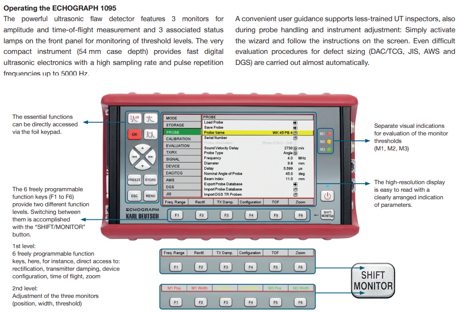
- The plain text menu provides intuitive, self-explanatory guidance for simple adjustments. A system wizard supports less experienced operators in probe handling and instrument setup, ensuring effective use right from the start.
- Advanced Measurement Capabilities:
- The ECHOGRAPH 1095 is equipped with essential ultrasonic testing features, including:
- Depth Compensation: Enhances accuracy by compensating for changes in sound velocity.
- Back Wall Echo Drop: Allows users to identify defects near the back wall of the material.
- The ECHOGRAPH 1095 is equipped with essential ultrasonic testing features, including:
- Optional Enhancements:
- The device can be further enhanced with optional features such as:
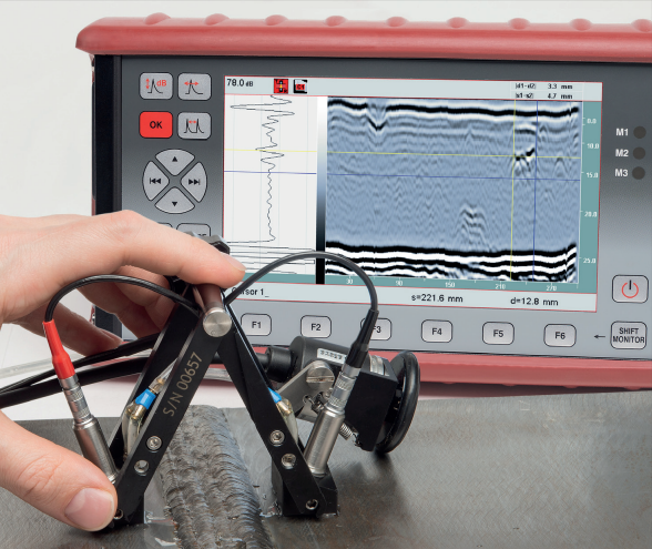
- Strip Chart Recording: Utilizes a linear encoder to digitally transmit the amplitude position, providing a clear graphical representation of measurement data.
- TOFD (Time-of-Flight Diffraction) Method: This technique is particularly effective for weld seam testing, enabling precise determination of defect location and size by analyzing diffraction signals from discontinuities.
- The device can be further enhanced with optional features such as:
- Matrix Storage and Visualization:
- Results from wall thickness measurements can be stored in a matrix grid. Each measurement point is assigned to corresponding cells, allowing for a color-coded visualization of flaw distribution. This feature is particularly useful for assessing residual wall thickness in pipelines, enabling quick evaluations of integrity.
- Additional Functionalities:
- The ECHOGRAPH 1095 supports various advanced adjustments, including DGS (Distance Gain Size), DAC (Distance Amplitude Correction), and TCG (Time Corrected Gain). It also offers multiple monitor gates with assigned indication lamps for streamlined operation.
- The pulse repetition frequency can reach up to 5000 Hz, enhancing measurement accuracy and response times.
- Advanced representation options include B-scan visualization and strip chart output for in-depth data analysis.
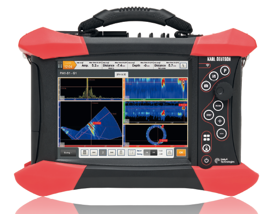
Portable Phased Array Ultrasonic Flaw Detector: GEKKO
The GEKKO portable phased array ultrasonic test system represents a significant advancement in non-destructive testing (NDT) technology. With its robust features and user-friendly design, the GEKKO is engineered to meet the demanding needs of various industries, providing efficient and accurate detection of internal flaws in materials.
Product Features
- Advanced Channel Configuration:
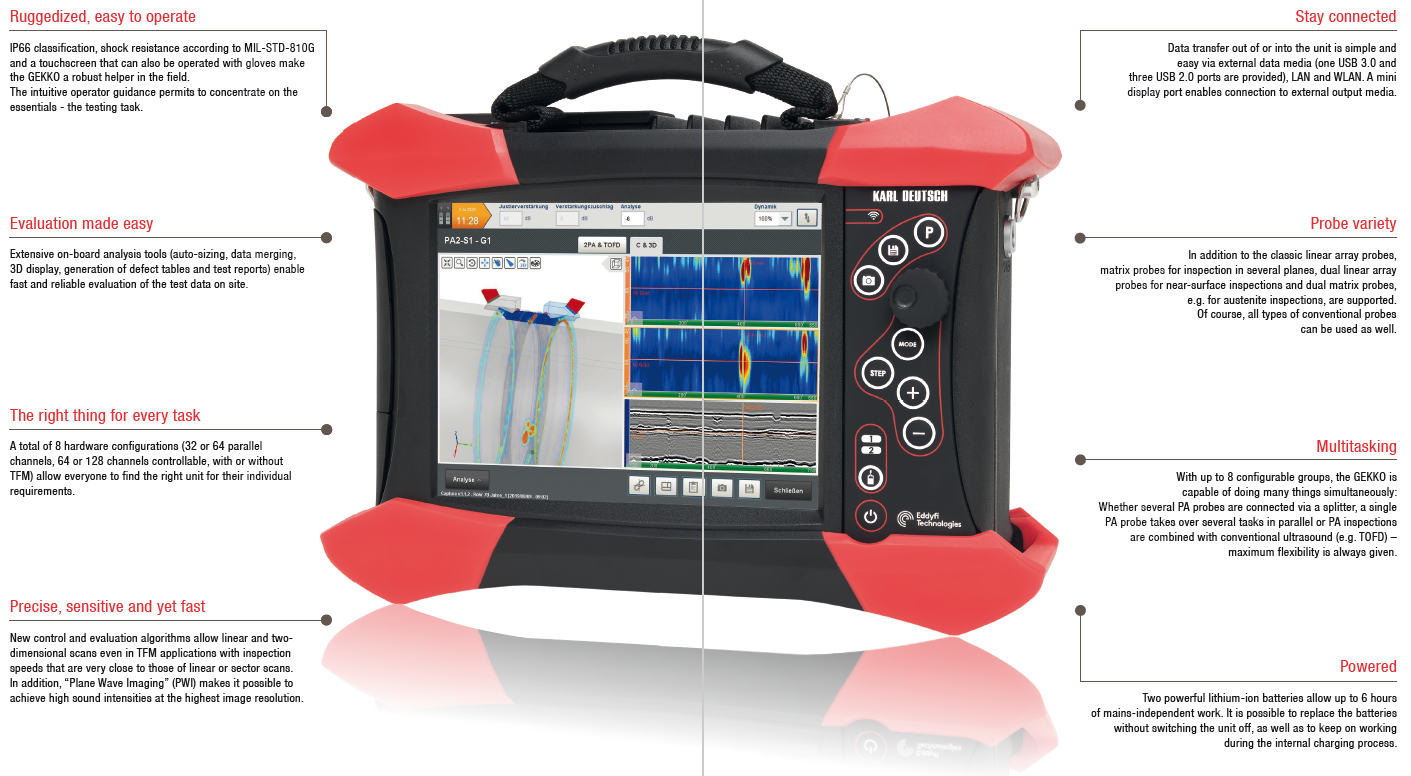
- The GEKKO supports up to 64 parallel phased array (PA) channels, along with four additional conventional connectors. This extensive channel configuration allows for versatile testing capabilities, accommodating a wide range of applications.
- Intuitive User Interface:
- Designed for efficiency, the GEKKO features an intuitive interface that facilitates quick parameter setup. Users can easily define individual and group examinations (up to a maximum of 8), streamlining the testing process and reducing setup time.
- Flexible Testing Applications:
- The system allows for rapid and flexible combinations of phased array applications with conventional techniques, such as Time-of-Flight Diffraction (TOFD). This adaptability enhances the range of tests that can be performed, making the GEKKO suitable for complex inspection scenarios.
- Total Focusing Method (TFM):
- The GEKKO was the first PA system to offer real-time testing using the Total Focusing Method (TFM). This innovative technique has been continuously refined, allowing for fast scans with x-y scanners and enabling high-sensitivity testing even with long sound paths. TFM optimizes signal reception and enhances defect detection capabilities.
- CIVA-Supported Parameter Creation:
- The system supports CIVA software for the creation of test parameters, enabling rapid calculation of delay laws for complex test problems. This includes configurations for matrix arrays and curved components, significantly improving setup efficiency.
- Extensive Result Representations:
- The GEKKO provides a variety of result representations, including A-scans, B-scans, C-scans, D-scans, top and side views, 3D representations, and dynamic curves. This comprehensive data visualization allows for thorough analysis of the material’s internal structure and any identified defects.
- Low Crosstalk and High Sensitivity:
- With extremely low crosstalk between adjacent channels (cross-talk attenuation > 50 dB), the GEKKO ensures a superior signal-to-noise ratio in A-scans, resulting in high-contrast B- and C-scans. This feature enhances the clarity and accuracy of the testing results.
- Encoder Inputs:
- The system is equipped with three encoder inputs, allowing for precise tracking and positioning during scanning. This capability is crucial for ensuring accurate measurements and detailed inspections.
- Runtime and Angle Dependent Sensitivity Adjustment:
- The GEKKO includes sensitivity adjustments based on runtime and angle, utilizing Distance Gain Size (DGS) principles. This ensures optimal detection sensitivity tailored to specific testing conditions.
